Chapter III. Some Networked Double Weave Designs, Using Tieups
It is time to get down to business!
The next chapters discuss some of the designs that can be woven in double weave using network drafting principles and how to achieve or alter them. The approach in this chapter is based on the use of tieups and works with a treadle floor loom, a table loom with levers to lift each shaft independently, or a dobby loom.
I think of two of the basic designs in double weave as "windows" and "checkerboards" and want to discuss them separately. Eight shafts are required to weave these designs.
I. The Windows Design
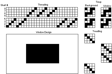
Figure 1 shows the threading, tieup, and treadling needed to weave an 8 shaft double weave windows design. A drawing shows what the drawdown looks like. The windows can be square or rectilinear, wide or tall. Eight treadles or eight dobby bars are required in the weaving. This is made explicit in figure 1 by expanding each part of the diagram so that it is easy to see what happens.
Figure 1. The Windows Design in Double Weave

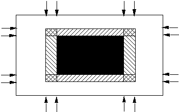
The transition zones when the design is networked are presented in figure 2. The vertical arrows correspond to transition in the threading. The horizontal arrows correspond to transition in the tieup or the peg plan. Single diagonal lines show where the woven area is a result of the transition in either the threading or the tieup. The crosshatch lines show where the woven area is a result of the transitions in both the threading and the tieup. These designs tend to have the rectilinear appearance of traditional double weave and not the curved shapes that are often seen in networking drafting.
Figure 2. Transition Regions in the Window Design
B. Computer Printouts for some Window Designs
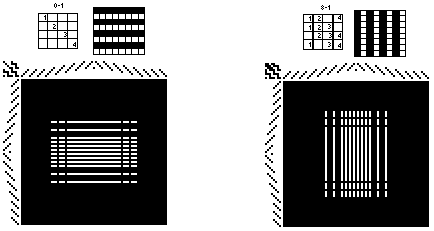
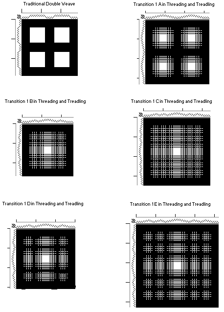
A variety of threadings have been used in the designs that are shown below and also in the next section where the checkerboard design is used. The first printout is for traditional double weave and is an expansion of the threading in figure 1. Notice that there is symmetry in the horizontal and vertical directions.
Figure 3. Some 8 Shaft Window Designs for Networked Double Weave
II. The Checkerboard Design
Figures 8 and 9 show the threading, tieup and treadling needed to weave an 8 shaft checkerboard design and should be compared with figures 1 and 2 of section I where the window design for double weave was discussed.
Figure 4. The Checkerboard Design in Double Weave
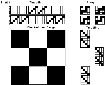
Figure 5. The Checkerboard Design Networked
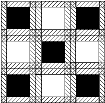
Here are some computer printouts for the 8 shaft double weave checkerboard design. The central checkerboard square has been enlarged in the last printout to improve the design. Even so, it seems to me that the overall impact for I C is not very pleasing.
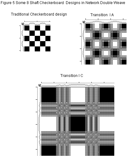
I decided to take one example, II B, to see if I could create a design I did like. Figure 6 shows the modifications I made. The first major change introduced a background around the checkerboard creating a window design where the window was in the form of a checkerboard. I needed to use 12 shafts to achieve this. The design was still confusing to me so I began to delete sections in the threading and treadling order and replace them with more of the background. The easiest way to do this was to shift threads from shafts 5-8 to shafts 9-12, always staying on the network. Notice also that the original checkerboard squares are larger and some are rectangular in shape. I felt that these changes produced a much more satisfactory double weave design.
Figure 6. The Development of a Design in Networked Double Weave 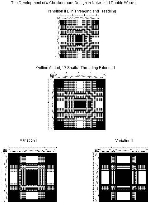
III. A Different Treatment for the Windows Design.
The window part of the designs presented in sections I and II of this chapter has been in traditional double weave with peg plan II producing the light top layer. However any of the other 254 peg plans could have been used for the windows. Figure 7 shows how the tieup can be altered substituting another peg plan for peg plan II.
Figure 7. Changing the Tieups for the Window Design
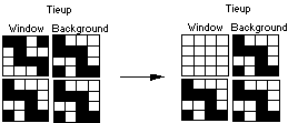
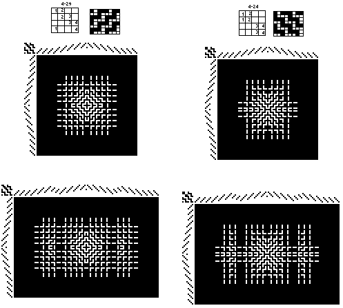
Here are some examples of what happens when this substitution is made. For each drawdown, the peg plan from Appendix A-1, with its identifying number and the 2 x 2 drawdown from Appendix B-1 are given. Remember that the window is now in integrated double weave, a single cloth layer. All of the designs are symmetrical.
Figure 8. Substitution of other Peg Plans in the Window Design
